Sidebar
Table of Contents
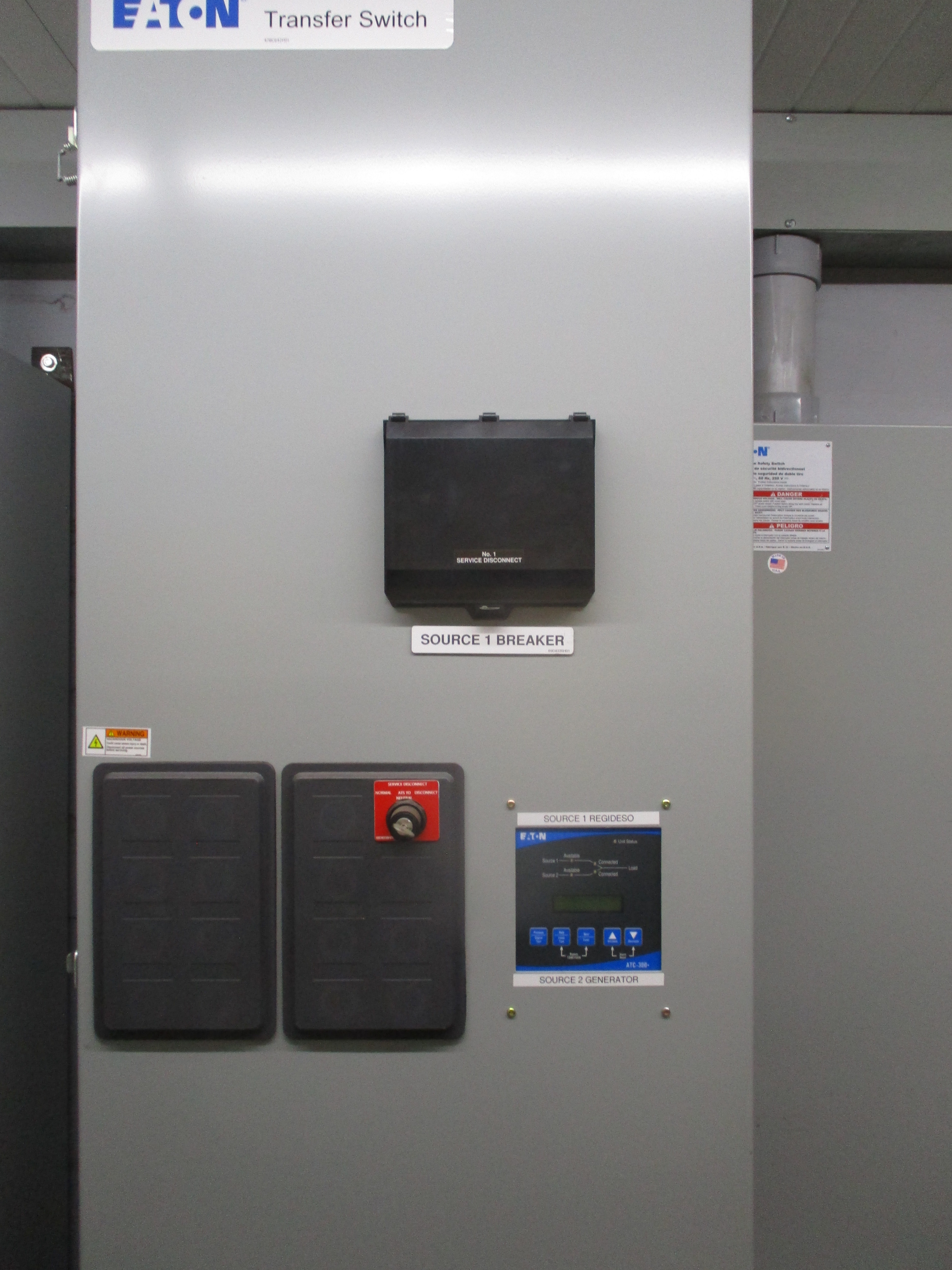
:: Auto Mains Fail Transfer Switch ::
An Automatic Transfer Switch (ATS) transfers power to a load between utility power and a standby generator, or between two alternate power sources (two generators, two utility sources, etc).
Most higher capacity ATS units are mounted in large cabinets, some as large as 30“ wide and 60” high, or more.
This is the primary disadvantage of a packaged ATS; its physical size is quite large compared to a set of contactors, which can otherwise be carried in an airline suitcase. That in particular makes the below designs more suitable for remote locations, as the parts can be carried in and assembled on location in a short time.
A secondary disadvantage of a packaged ATS is that the contacts are typically listed for a maximum of 5000 transfers at rated load, at which point the contacts must be replaced, and frequently the electro-mechanical actuator as well. In locations where electric power is reliable, this is typically not an issue as 5000 transfers will take several decades to accumulate. In locations with unreliable power this number of transfers can be accumulated in just two or three years.
Contactor-Based ATS :: Pro & Con
Automatic transfer switches for standby generators using industrial motor-control contactors have the advantage of simplicity and long-life, typically over 500,000 operations at rated load in the 400A range, increasing in smaller Ampere size ratings. They also use typical off-the-shelf components that are commonly available.
The primary disadvantage is that they do not meet National Electrical Code requirements in the United States for Automatic Transfer Switches for emergency and legally required standby power use. They do not satisfy the two requirements of NEC [700.5(C)] and [701.5(C)] (2011):1)
- They are not manufactured as Automatic Transfer Switches (ATS) or approved by a testing lab for emergency power system use.2)
- They are not mechanically held.
Optional Standby systems as defined in [702.4] are not bound by these legal requirements for transfer switches.
Motor Contactor Selection
The appropriate size of motor contactors should be selected based on the load served and the genset size. The 400A frame is a good general purpose selection, but smaller or larger can substituted, however circuit breakers and wire sizes must be adjusted appropriately. Recommended source: FactoryMation.com (225A frame and larger have 100-240VAC/DC coils)
See warnings below
ComAp InteliATS Controller
 This automatic transfer switch uses a ComAp ATS Controller combined with motor contactor switching to provide a fully-featured ATS with full metering & history logging, and can also be remotely monitored.
- InteliATS 70 adds PLC logic blocks
![]()
Relay Logic ATS
Using the same motor contactors, this ATS is instead controlled by "Relay Logic". It is slightly cheaper, but requires more wiring and has less flexibility.
 One or more multi-meter(s) can be added, but are not shown in the wiring diagram.
![]()
:: WARNING ::
Follow all applicable electrical codes. Consult a licensed electrician or an electrical engineer for assistance selecting appropriate wire size, circuit breaker, and contactor ratings. These plans assume that you have the necessary expertise and experience, or that you will consult with and work under the supervision of a licensed electrician or experienced electrical engineer, for assembly and implementation. Failure to do so can result in serious personal injury, damage to property, destruction of generator sets and wiring, even causing fires and death.
Page Tools

Copyright © Alan Shea, 2011-2026